At some point, we need to add power to our model railroad empires. Power for the locomotives, for lighting, for signaling, and perhaps for animation. In the pages that follow we will consider: the type and size of wiring; wiring connections; simple wiring; complex wiring situations; DCC – what it is and how it differs from plain DC; DCC wiring and tools.
TYPE AND SIZE OF WIRING
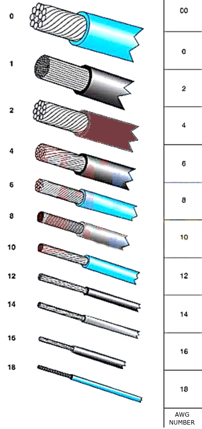
The first thing one needs to consider is the type of wiring that should be used. AWG stands for American Wire Gauge. Number 1 AWG wire size is large, whereas 14 AWG, is smaller. Thus, the lower the number is, the larger the wire size, and the higher the number is the smaller the wire size.
No matter if you're wiring your layout for DC or DCC, the wire size has to be adequate to handle the current (amperage), and the voltage supplied to the rails.
Using solid wire, or stranded? Stranded (or bundles of smaller wires inside insulated wire) is preferred over solid wire. The reason is it is more flexible to work with and less likely to break connections. Having said this, solid wire is often used to serve as the feeders to the rails.
Another factor to consider in buying wire is the insulation of the wire. You want to use wire with PVC (Poly Vinyl Chloride) insulation, which is softer and has a higher temperature rating. If possible, use house wiring, or Machine Control wiring, with thick insulation for bus wiring. This type is what is typically found at big box stores, such as Home Depot, or Lowes, on spools ranging from 100' to 500' or more, and often sold by the foot. Electrical supply firms also sell wire with PVC insulation.
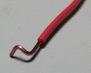
To actually connect wires to the track, it is best to solder them to each other. Rail joiners with wire attached are available but are not recommended as the best method. To put in track feeders, drill a hole next to the rail between two ties. Feed the wire down through the hole and then bend the wire like this for easy soldering to rails. Then using a soldering iron and thin solder, hold the wire to the rail with the soldering iron and touch the solder to both of them. A small screwdriver is then used to hold the wire and solder to the rail, as the solder cools. It takes a bit of practice... but once you do a few of these, you can make wire connections almost invisible.
WIRING CONNECTIONS
When wiring a simple layout for a single operating train, two wires from the power pack to the track could be sufficient. However, the train may run slower as it gets further away from the power pack, then speed up again as it gets closer. This is due to the voltage drop of the electricity going through the rails. The drop increases as the distance from the power supply increases. The way to help eliminate that is with BUS WIRING.
Bus wiring is installing a heavier bus wire following the track. Then running the feeder wires from the bus to the track, spaced 2-3 feet apart. This will get a more even flow of electricity through the rails and train control will be smoother.
We have discussed attaching the wire to the rails, but what about those feeder wires to a bus wire. Well, there are several ways.
- You can simply solder wires together. By removing some insulation on the bus, then wrapping bare feeder wire around the bus and soldering them together, you have a connection. This is fairly permanent but could be unsoldered if the connection needs to be broken.
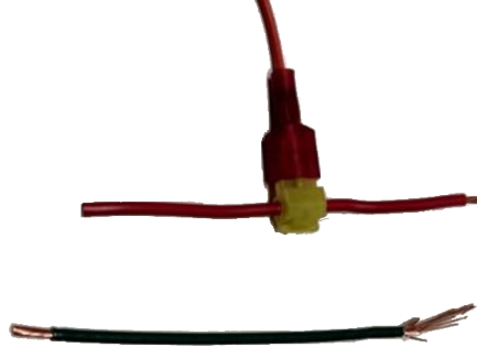
- Suitcase connectors do not require soldering but are not easily removed. They work by cutting a piece of metal through the insulation of both wires, thus connecting them together. No insulation is needed to be removed!
- Wire t-tap and spade connectors are another type of connection that does not require soldering and is easily removable if needed. They are a two-piece connection with the t-tap being crimped on the bus wire. Then a spade/blade connector is crimped onto the bare end of the feeder wire and inserted into the t-tap connector. The feeder can be removed from the t-tap easily if required.
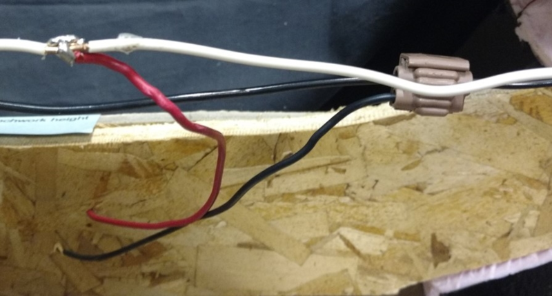 Soldered joint
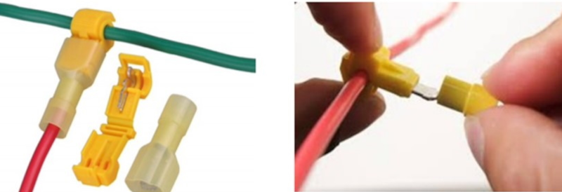 Suitcase connector T-tap and spade connectors
There are lots of other types of connectors, but these are the most common and give the greatest flexibility and reliability! 3M offers an array of connectors that are of high quality. Many imitations can be found on the Internet as well.
SIMPLE WIRING DC
Let’s look at some examples of simple wiring on a simple one-train layout. In the example below (below) is a typical beginner layout of a loop of track with a siding. Simple wiring of the power pack to the track is usually sufficient for operating the train. The siding can be powered, or isolated with a toggle switch if needed (not shown). Don't forget that with this wiring, we can get that voltage drop when the train gets further away from the power pack.
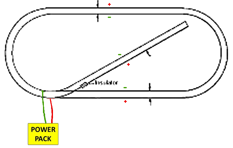
Now let’s look at this same layout with a bus line wiring (below). The red and green lines are our bus lines, one for positive, one for negative. The feeder wires are then connected from the track to the bus lines, keeping the rails all connected to the SAME bus, inside rail to negative, outside rail to positive. While this is more work and wiring, the train will run better because the electricity flows better to all track sections.
COMPLEX WIRING SITUATIONS
There are several complex wiring situations that must be tackled, depending on your track plan. Parking, reverse loops, Wye’s, and running several trains at the same time are the few we’ll look at.
PARKING LOCOMOTIVES
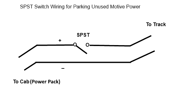
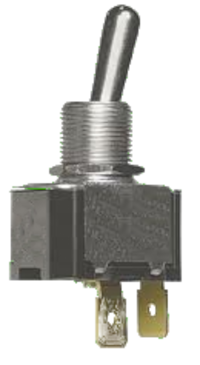
There are many times when you want to ‘park’ a locomotive or an entire train. Passing sidings, stub-end sidings, and yard tracks are some common examples where you might want to pull a locomotive or entire train in and then cut the power off so that you can work another train. The wiring for such examples is easy. Simply isolate the track in question with plastic rail joiners on each end, and when running power to the isolated track, insert an ‘on/off’ switch between the power pack and the track. When flipped to the ‘on’ position the track has power and when flipped to the ‘off’ position the track is ‘dead’. Most often a "Single Pole/Single Throw" (SPST) toggle switch mounted on the fascia is used for this purpose.
REVERSE LOOPS
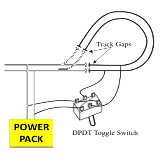
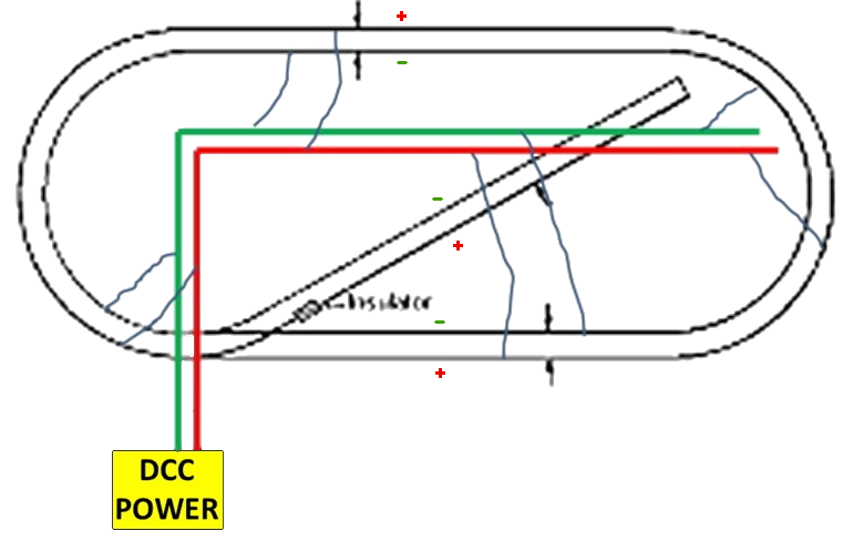
A reverse loop is when the track turns around on itself, making the train go back the way it came. This creates an electrical problem because the track rails, which are positive/negative now connect to each other in the opposite polarity! This causes a short and will damage power packs and locos. With reverse loops, both rails must be "gapped" at each end of the loop. A separate "Double-Pole/Double-Throw" (DPDT) toggle must be wired to the reverse loop and thrown while the train is stopped in the loop. This changes polarity for the rails, to allow the train to exit the opposite end of the loop. Or, a suitable "Auto-Reversing" circuit board can be used in place of the toggle.
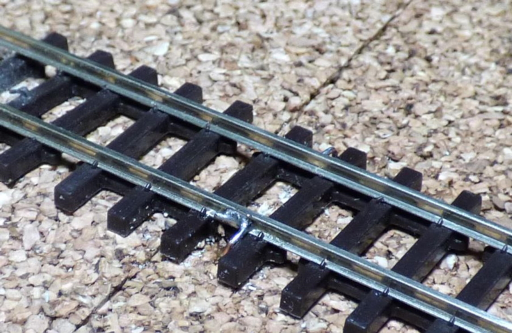
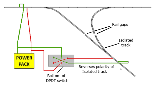
In the picture... you see that we have placed gaps or rail insulators on the looped section of track. This isolates this section from the main track and now has no electricity flowing to it. Note on the second picture, how the polarity loops back on itself, causing a short.
WYE TRACK
A wye track is similar to a reverse loop in wiring. The “tail” of the wye needs to be isolated and a DPDT switch installed to control the track polarity.
MULTIPLE TRAIN CONTROL – CAB CONTROL
You have advanced a bit and now you want to run two trains on your layout. Is that possible? YES!!! There are two ways to do this: wiring for cab control and installing a digital command control (DCC) system.
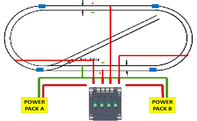
"Cab control" or "block control" requires two or more power sources. A "block" of track has one or both rails isolated at each end of it, and is isolated between turnouts. In this case, you can use Atlas selector switches (pictured), and other control switches they sell, to divide the layout into blocks to route the power from one power pack, or another. These are OK for small layouts such as 4' X 8' or a bit larger.
Blocks and Cabs using Atlas Selector Switches.
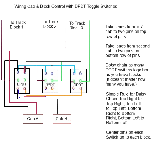
Instead of the Atlas Selector Switches you can use a good grade of industrial "Double Throw/Double Pole, Center Off Toggles", or "On / Off / On' switches, mounted in control panels with the "Track Diagram" painted on it. But this limits you to only 2 Throttles! Another option is to use 2-pole, "adjustable" 12-position rotary switches, which allow you to have as many as 12 throttles, or power sources, for "block" control.
The diagram below shows typical wiring for Cabs and Blocks using toggle switches.
Although DC Analog wiring for block control requires more wiring, most of the layout can be "common" rail wired, having one continuous rail all wired from one bus wire and feeders and wires to the other rail run through toggles or rotary switches. This was how most large home layouts were wired in the past. Reverse loops and wyes must have gaps in both rails.
Disadvantages of DC or Analog:
With this type of control, you always have to align the toggle switch for the cab, or throttle you’re running with for each block, to let the train you’re running progress around the layout. All wires should be numbered, or color-coded, to trace in case of a break in the circuit.
DCC? WHAT IS IT?
DCC stands for Digital Command Control. Where DC-analog was known as Block Control because the track was sectioned into blocks, DCC does not need blocks and we can run many trains on the same track with total independent control.
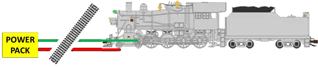
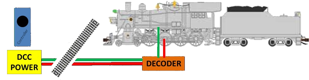
As the picture shows – DC analog has power to the track that then goes to the locomotive directly. DCC is different –
DCC is not only supplying power to the locomotive but also sending command signals to the receiver (Decoder) in each locomotive. These commands instruct the locomotive to run fast/slow, forward/reverse, turn on ther headlight etc.. The decoder is installed IN the locomotive. The receiver (Decoder) then converts the bipolar square wave of DCC to DC for the motor circuit of the decoder, in addition to reading the DCC instructions. Thus, the elimination of having to control individual blocks of track, with toggle, or rotary switches! As one manufacturer describes it, "Control your Trains, Not your Tracks". With DCC, you keep using the same throttle for controlling the train you're running, no matter where it is on the layout. DCC also gives you SOUND! Now your trains do not run in silence. Refer to the pages on DCC for this website.
https://www.nmra.org/dcc-working-group DCC in most cases uses less wiring. Two bus wires of different colors 14 AWG or larger, can be run under the layout, or roadbed surface. Then smaller 18 AWG "feeder wires" of the same colors, soldered to the outside of each rail, then run down and are attached to the bus wires below. Run feeder wires from each 3-foot section of flex track. Smaller sections, or pieces of track should also have "jumper" wires run to each rail, from the previous 3-foot section of track, (* so long as it does not connect 2 zones, or power boosters). By doing this, you ensure good continuity throughout the rails, over the entire layout. Some manufacturers recommend using stranded wire 14 AWG in size for bus wires, and 18 AWG for the feeder wires to the rails.
DCC layouts, should NOT use "common rail wiring". DCC wiring is bus wiring. Also refer to
TN-9 for more information on wiring for DC and DCC.
Large layouts with DCC might require two or more boosters to supply power. The more track and equipment you have with DCC Sound decoders, or cars with lights, etc., the greater the chance that with one booster, the overload circuit breaker of the unit will trip, shutting down the whole layout. In such cases, the trackwork is divided into electrically-isolated zones, each powered by a booster. These zones are wired and serve a different purpose than the blocks on a DC-powered layout.
When using more than one power booster, both rails have to be gapped at each end of the Zone, and must not be connected to the previous power booster either. So, separate bus and feeder wires need to be run to each Zone. In this case, if a train derails in one Zone on the layout and shorts out, tripping that power boosters circuit breaker, locomotives in the other Zones, keep running.
Just remember to keep the bus and feeder wire polarity (phase) the same for each Zone. A good recommendation is to use different colored bus and feeder wires for each Zone, which makes it easier to troubleshoot problems or find open circuits, should they occur. Power boosters are usually "daisy-chained" with data cables on most DCC systems.
To wire Reversing Loops, you need to do the same as for DC wiring, that is both rails must be gapped at each end of the loop. A "double-throw/double-pole toggle" can be used, or you can purchase a separate "Automatic Reversing Card" such as "Tony's" (DCC Specialties) PSXAR reversing units. Two wires from the bus wires go to the "input" side of the circuit, and two wires from the "output" side of the circuit card go to the reverse loop. In some DCC Systems, the boosters sometimes now have a reversing circuit built-in, so check your systems manual.
To prevent overloads, you might need to have on/off toggles on your engine and storage tracks to shut off engines and equipment when not being used. Overloads can create a situation in which your power booster fails to reset after a short circuit.
TIPS & TOOLS OF WIRING
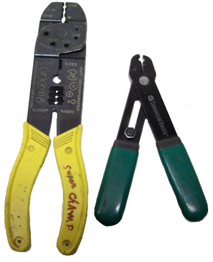
When buying tools to strip wire, or crimp connectors on wire, don't skimp and buy "cheap junk". They will only cause you more grief than they are worth!
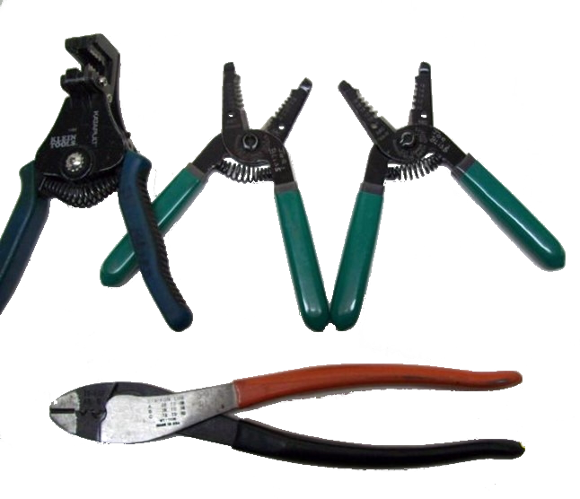
Home Depot does carry the "Commercial Electric" Brand of "T-Strippers", but other brands such as "Klien" are better. The jaws are marked with the wire gauge sizes and designed only to cut through the insulation, not the wire. Use the appropriate marked slot for the wire size. Below is a photo showing T-Strippers, a Klien automatic wire stripper, and a "Sta-Kon" crimper. These are the ones to buy, not the cheap adjustable ones, or the stripper/crimper shown in the next photo.
When stripping wire, make sure it's stripped to the proper length for the terminal you’re using, and if you nick out more than 1, or 2 strands of wire, cut the end off, and strip it again correctly. When crimping a spade connector or lug connector on wire, give it a pull test, if it comes off easily, you have a miss-crimp, and will get intermittent continuity from the connection.
Credits
Many thanks to the members (particularly Joe Bliss) of Division 6 of the North Central Region, NMRA for permission to use their content in this part of the Guide.
Updated 28-Feb-2023