Many a child has set up train tracks (plastic, wooden, or metal) on the floor and spent hours playing with trains. However, at some point, those of us who stay with the hobby want to have a more permanent home for our miniature railroads. That is the point when we have to tackle benchwork.
Like so many things in this great hobby, there are many ways to create stable benchwork. We will show two of the more common ways. Both produce very good results. Although some carpentry skills are needed, and some common carpentry tools will also be necessary, one does not have to be an accomplished carpenter to build serviceable benchwork.
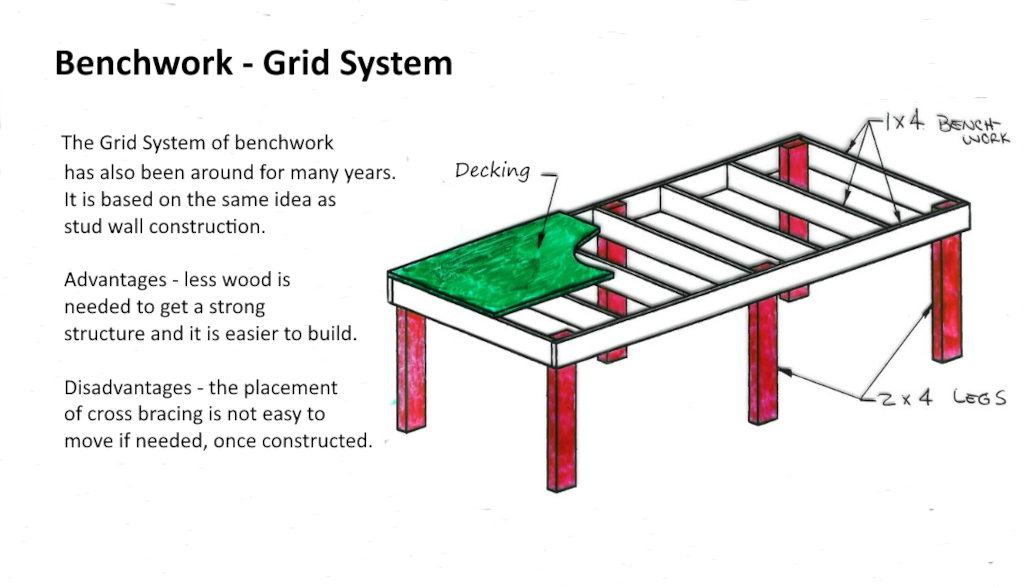
Many modelers start by building some simple framing to hold a 4’ x 8’ sheet of plywood decking and inserting four legs at the corners. Add some bracing on those legs for stability and you are ready to go. Since this is a common starting place, we will indeed start by describing this type of benchwork in more detail.
OPEN GRID BENCHWORK is like building a wall or grid out of 1” x 4” (25mm x 102mm) boards. (1”x 3” can also be used.) Two sides with stringers/cross braces in-between and spaced about every 16-24 inches. Screw these together, place “sideways” and support with legs and leg supports. (Decking screws are excellent for this and countersink the heads.) This type of benchwork can also be attached to the wall for extra support and fewer legs.
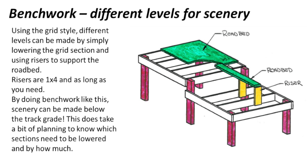
If your design has features of valleys or rivers that will be below the track level, an open grid allows that section of the layout to be easily recessed! Open grid benchwork also gives a better edge to the layout for adding a fascia board later.
Open grid benchwork does use less wood than other systems, but it is not as easy to modify if something under the layout is in the way of a stringer/cross brace.
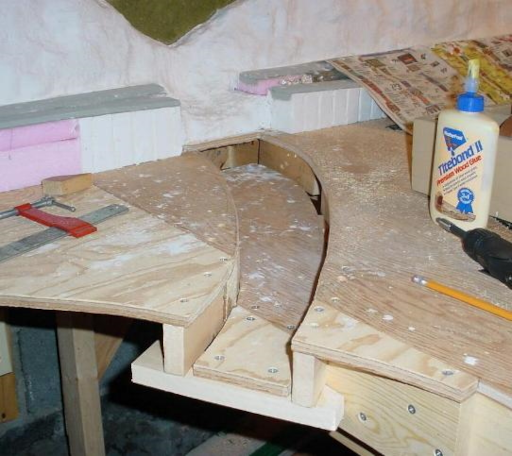 A section of the decking has been cut out and lowered to form the bottom of a stream bed.
A comment on benchwork height is appropriate. This is a matter of personal preference and the height of the modeler. However, somewhere in the 38” (96.5 cm) to 52” (132 cm) range is comfortable for most modelers.
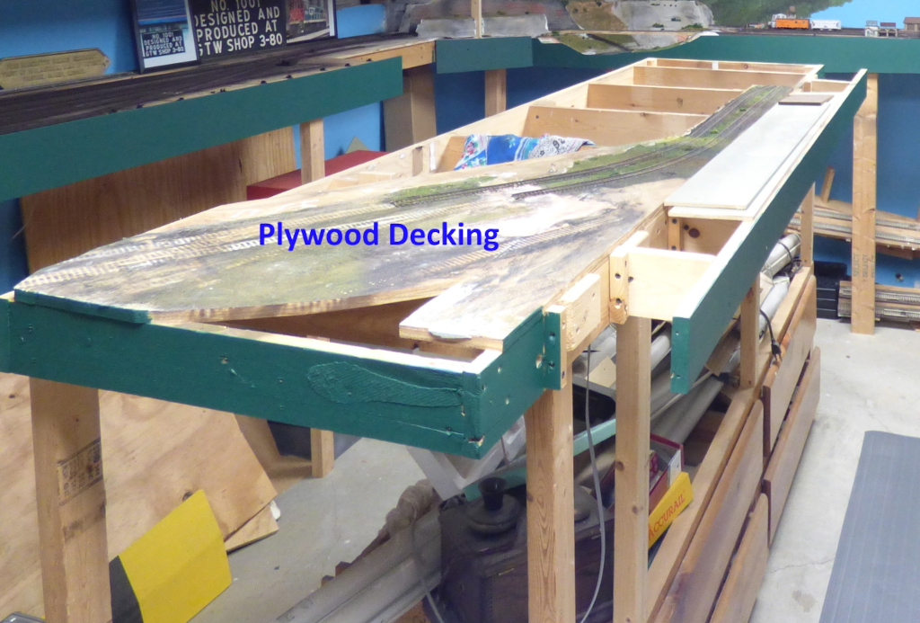
Once the framing is done, it is time to add the decking. Plywood is the most common choice. Depending on the number of cross braces used, thickness in the range of 5/8” (15.9 mm) to ¾” (19 mm) is suitable.
Although plywood might be the most often used decking, it is not the only choice by far. Some modelers use hollow core interior doors while others love Homasote for its sound deadening benefits.
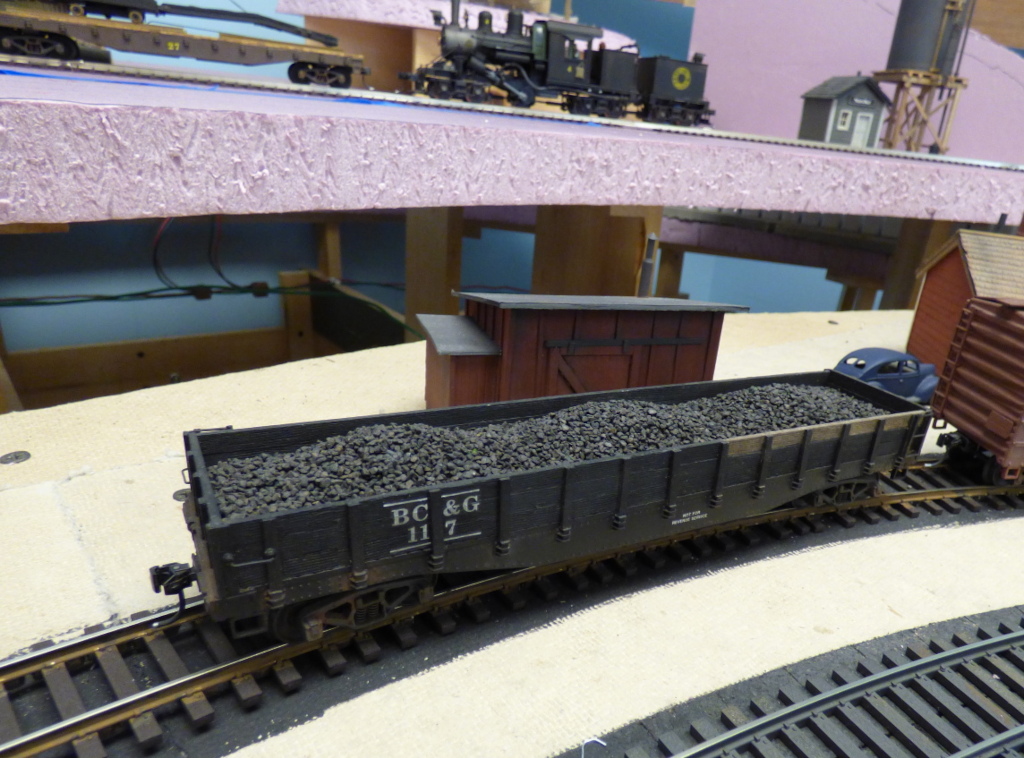
Of late, 2” (50 mm) thick sheets of pink or blue foam insulation boards have become popular. The benefits of the foam are that it is sound deadening, lightweight, and can easily be carved out to produce ‘below ground level’ scenic elements such as ponds and streams. Although not really needed for structural support, many modelers lay down a thin sheet of plywood (¼” or 6.35 mm), or similar thickness Luan plywood, and then glue the foam board to that using a ‘foam friendly’ adhesive. The thin sheet of plywood is useful when trying to attach ‘below the benchwork’ items such as wiring and turnout controls. Even a thin sheet of wood accepts small wood screws for this purpose. The attached photo shows a foam sheet with no plywood serving as the decking for the upper level of this model railroad.
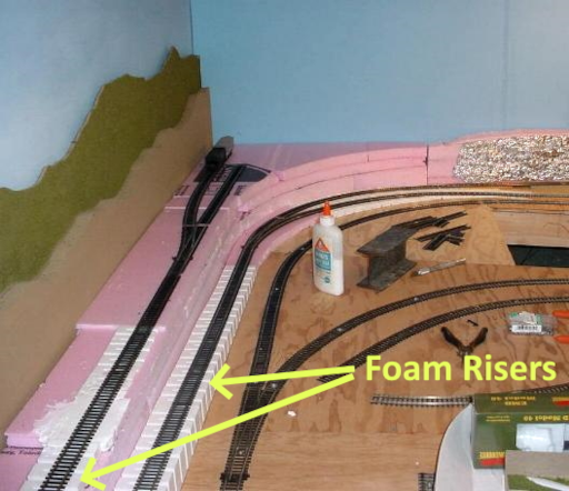
We have mentioned how a modeler can cut the decking out to make ‘below ground level’ scenic elements. For scenic elements that rise above ground level, stacking pieces of foam on top of one another works well.
Having track access to these higher levels can be accomplished by using foam risers offered by Woodland Scenics and others. This photo illustrates how this is accomplished. More information for creating scenic elements can be found in
Part 6 of this Guide.
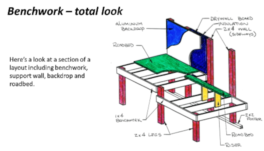
The diagram below shows another idea for how to prepare for 3-D scenery.
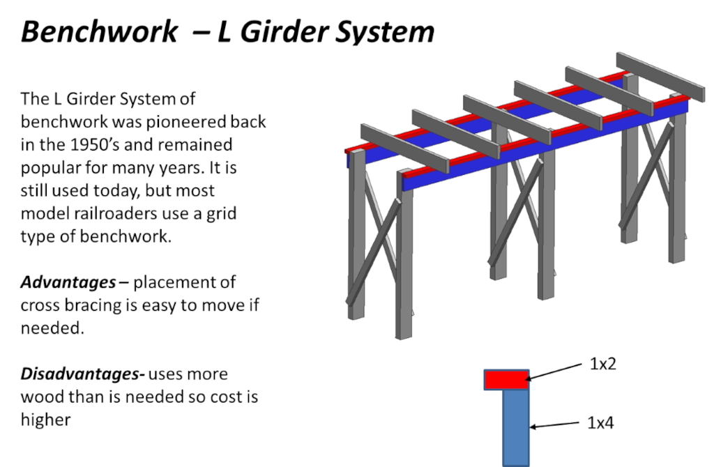
L-Girder Benchwork provides flexibility and strength. Using 1x4 and 1x2 lumber boards, you screw them together to make an L shape. Two of these pieces on legs with supports form the base structure. Then stringers/cross braces are placed on top to give the framework for track. Decking of plywood or other material can be attached directly to the cross braces or supported by risers as with the grid system. These upper boards are moveable to where they need to be or to avoid something that needs to hang down under the layout (turnout motors or wires). L-girder benchwork is generally free-standing. Because the cross braces are attached to the L-girder from below with screws that are accessible, they can be moved easily at any point in the layout construction.
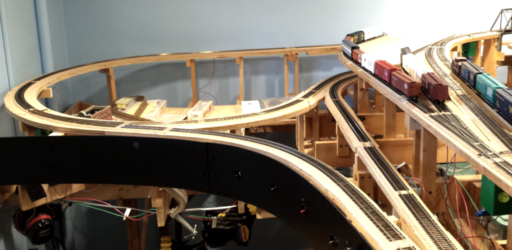
The following photo, taken by Bruce DeYoung, MMR®, features Chuck Diljak’s Wyoming Valley RR in HO Scale. It shows the L-Girder technique in action.
BENCHWORK BASICS – Once you decide which benchwork style will work best for your design, there are some tips that apply to both of the techniques covered here. These will help make building benchwork better:
-
Always use screws, not nails! Drywall screws are great for putting benchwork together! They are stronger than nails and make it easy to take apart, if necessary. The best length of screws is 1.5” (or so).
-
When using screws, drill a counter-sink pilot hole first. The wood we usually use is pine and it can split easily. Drilling pilot holes and using a counter-sink at the same time helps to keep the wood from splitting and gets the screw head into the wood.
-
When buying your wood boards, 1x4 or 1x3, do not buy the cheaper type with rounded edges. These boards are usually not very straight! It’s better to spend a bit more and get the higher quality wood. Also, the longer the boards, usually the straighter they are! Thus, buy boards as long as possible, even if you have to cut them to get them in the house.
-
For legs to support your benchwork, 2x4’s work great and you can usually get 2 legs per 8’ board. 1x3 or 1x4 boards screwed together to form an L shape will also work well. Depending on how wide your benchwork is, angled brace legs that go from the front edge to the base of the wall work well and eliminates legs getting in the way at the front of the layout.
-
Your benchwork needs to be level! Use a level when attaching your legs.
-
Backdrops help to keep viewers’ eyes on your model railroad rather than on distracting objects in the room. Your backdrop can be several different materials, drywall, hardboard, and even sheet aluminum. It may also be a combination of these materials. Sheet aluminum has the advantage of being seamless for a long distance but needs support behind it to keep it flat and steady. Hardboard (Masonite) works well and can bend some if needed, but is usually only good on one side, so a free-standing backdrop would have to be double pieces for painting purposes. Even though we are nowhere near the scenery part of building your layout, now would be a good time to paint your backdrop. Painting it sky blue now will save you from getting paint on your track or structures later on!
Tools
Basic carpentry tools are needed. These include a hammer, several screwdrivers (or power screwdriver with interchangeable bits), carpenter’s square, level, and measuring tape. Additionally, the following list of tools will prove helpful:
-
2 saw horses (optional, but make cutting wood to length easier)
-
1 circular saw, saber saw, table saw or hand cross-cut saw. Any will work, but if you are buying your first saw, a saber saw, while not as handy for this project, will be the most useful in the majority of model railroading applications
-
1 3/8" reversible electric drill
-
1 bit to fit drywall screws
Addendum
For those who have limited space but still want to get some experience building a small model railroad, you might want to look at this ‘under the bed’ approach. The sample shown and the instructions are provided by the members of the Garden State Division of the Northeastern Region, NMRA.
Instructions for building this small layout can be found
here.
Credits:
Many thanks to the members of Division 6 of the North Central Region, NMRA for permission to use content in this part of the Guide. The diagrams contained herein and some of the other content were prepared by them.